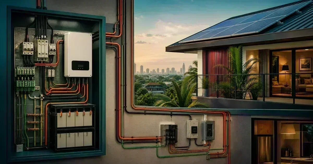
Learn how to read a residential solar wiring diagram in the Philippines, identify energy paths and protection zones, and prepare questions without working on live conductors. For the next planning step, see typhoon-proof solar installation guide.
Read the diagram as energy paths
A useful diagram shows where energy comes from, where it is converted, where it is stored, and which loads receive it. Typical labels include PV array, DC isolator, charge controller or hybrid inverter, battery bank, AC distribution board, backup loads, grid connection, grounding and surge protection. The diagram should also show equipment boundaries rather than relying on a vague picture of “panels to inverter.” For a personalized system check, use the CalcSolarPH solar calculator.
Understand the main protection zones
Protection is a coordinated system. PV-side disconnects, overcurrent protection, surge protection, battery-side protection, inverter input and output protection, and backup-circuit protection each have a purpose. The correct rating depends on the equipment manual, conductor ampacity, fault current, installation method, and local requirements. A breaker that physically fits is not automatically electrically suitable.
Look for missing information
A diagram deserves questions when it omits conductor sizes, voltage ratings, polarity, grounding method, neutral treatment, battery isolation, cable routes, or the relationship between the backup output and the main distribution board. Missing labels are especially serious when a system can operate in both grid-connected and islanded modes. For the next planning step, see solar cable sizing and voltage-drop guide.
Use color and labels consistently
Every installed cable should be traceable to the diagram and labeled at both ends where practical. Do not assume that a familiar wire color proves function. Confirm the manufacturer’s terminal labeling and the electrician’s documented identification. Photographs taken before covers are installed can make later maintenance much safer.
Do not use a receptacle as a transfer device
A portable inverter or battery system must never be connected to a building circuit through a wall outlet or an improvised male-to-male lead. Safe transfer equipment prevents unintended energization of circuits and protects utility workers. If the proposed diagram cannot clearly explain isolation, stop and ask a qualified electrician. For the next planning step, see solar backfeed and transfer-switch safety guide.
Prepare a diagram review checklist
Ask who designed the diagram, which exact manuals were used, how the neutral and protective earth are handled, what happens during a grid outage, how the battery is isolated, which circuits are backed up, and what tests will be recorded. The goal is not to memorize symbols; it is to identify assumptions before they become hazards.
A practical DIY evidence log
Keep a dated record of assumptions, measurements made from a safe location, photos, model numbers, weather, alarms, and questions for the installer. Good records make troubleshooting faster and reduce the temptation to experiment with energized equipment. For the next planning step, see live DC measurement safety guide.
Frequently Asked Questions
Is a solar wiring diagram the same as an installation instruction?
No. A diagram communicates architecture, while the manufacturer manual and qualified installer define the approved installation procedure, settings, clearances, and tests.
Why is neutral treatment important?
Grid-connected and backup modes can use different switching and bonding arrangements. The exact design must follow the inverter manual and applicable electrical rules.
What should a homeowner keep?
Keep the final single-line diagram, equipment manuals, serial numbers, protection schedule, commissioning record, and photos of labeled equipment.
Use the CalcSolarPH calculator for an initial estimate, then compare the result with the solar products catalog and have the final electrical design reviewed by a qualified professional.